Dependency Map
The dependency map is a tool that allows you to visualize the service-resource model of configuration items (CIs).
The map has two main components:
- node – a configuration item. It is displayed as a square in the colored box, indicating the current operational state of the CI.
- relationship – the relationship between items. Relationships between CIs are displayed with simple-directional or bidirectional arrows.
The hierarchical levels of components are determined by the CI types or CMDB classes, depending on the simple.ci.dependency_map.display_mode system property value. Custom configuration through a script is also possible.
- If the property value is type, creating a new CI Type results in adding the next lower level to the model.
- If the property value is class, creating a new CMDB Class may result in adding a new lower level to a model that includes this class.
- If the property value is custom, the dependency map is built based on the getCustomDependencyMapData script include available at the
\{your instance URL\}/record/sys_script_include/174792342812873874address. With this script, you can define a criterion for the differentiation of levels on the dependency map, as well as other settings of the map. See the Configure connections section to learn more.
There are two ways to open the CI dependency map:
- Click next to the Source CI or the Recipient CI field on the CI Relationship form to see the hierarchical place of your CI on the map.
- Use URL
https://instance.example.com/visual/dependency?sys_id=XXXXXXXXXXXXXXXXX&essence=sys_cmdb_ci&script=CI, where X is the CI ID. The link formed in this way can be used in the navigator for quick access to the map, in user interface actions and widgets, if necessary.
You can create your custom map using the following parameters:
| GET-parameter | Description |
|---|---|
| sys_id | The record ID. |
| essence | The system name of the Configuration Items (sys_cmdb_ci) child tables. |
| script_id | The name of the server script that returns the required data set on the map. The data set must be in a certain format, divided into nodes and transitions (relationships) between them. |
Correlation of color-coded frames and CI operational states
| Frame color | Operational state |
|---|---|
| Green | Available |
| Yellow | Degraded |
| Red | Unavailable, Maintenance |
The arrows with a label specified are blue on the map. Move the pointer over an arrow to see the Connector label. Arrows with no label are black.
You can drag the CIs on the dependency map by right-clicking and holding a CI. This will help you arrange complex maps. The map returns to its initial state when the page is refreshed.
Create a CI Relationship from Dependency Map
To add a new CI Relationship from the Dependency Map view, follow the steps below:
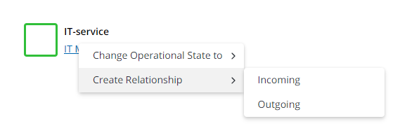
- Right-click the required CI and click Create Relationship in the context menu.
- Select one of the options:
- Incoming – to create an incoming connection to your CI
- Outgoing – to create an outgoing connection from your CI.
- Fill in the form.
- Click Save or Save and exit to apply the changes.
You can also create a relationship between CIs in the CMDB Relationships (sys_cmdb_relationship) table. See the CI Relationships article to learn more.
Change the CI operational state from Dependency Map
To change the CI Relationship operational state from the Dependency Map view, complete the steps below:
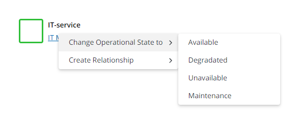
- Right-click the required CI and click Change Operational State to in the context menu.
- Select one of the CI operational states. For more information, see the Configuration Management Database article.
Configure connections
To configure connections between CIs on the dependency map when the getCustomDependencyMapData is used, the following properties of the data.connections JSON array component are used:
| Property | Type | Mandatory | Description |
|---|---|---|---|
| source | string | Y | Specify sys_id of the source node. |
| target | string | Y | Specify sys_id of the target node. |
| type | string | N | Allows to specify the connection color. Available values:
When |
| is_bilateral | boolean | N | Determines whether the connection is bi-directional. Available values:
|
| label | string | N | Allows to specify the text that appears when a user hovers over the connection. |
Style object
To configure the appearance of connections, the style object in the data.connections JSON array component is used. The object supports the following properties:
| Property | Type | Mandatory | Description |
|---|---|---|---|
| strokeColor | string | N | Determines the connection color when a user does not hover over it. If no value is specified, the system uses either the |
| strokeColorHover | string | N | Determines the connection color when a user hovers over it. If no value is specified, the system uses either the |
| dash | string | N | Allows to specify a dashed line template as a space-separated row of numbers. This property complies with the dashstyle attribute as per VMS specification. |
| width | integer | N | Determines the thickness of the dashed line. Default value: 1 |
Default connection colors
If no values are given in the data.connections array, in the type property or the strokeColor and strokeColorHover properties of the style object, the system uses the following default colors:
- the
labelproperty is not specified –#2E3238 - the
labelproperty is specified:- when a user does not hover over the connection –
#66BFFF - when a user hovers over the connection –
#0078CF
- when a user does not hover over the connection –
If the type property contains any value other than labeled, the system uses the value when a user does not hover over the connection, and uses the default value when a user hovers over the connection.